中文
中文 English
 Español
 Русский
 Français
 português
 العربية
- 1
- 2
- 3
- 4
- 5


Tel:+86-311-8648-658
Fax: +86-311-8648-668
Mail:delin@worldbrandcorp.com
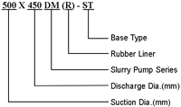
.jpg)
| Type | Allowable Mating Max. Power(kW) | Material | Clear Water Performance | Impeller | |||||||
| Liner | Impeller | Capacity(Q) | Head(H) | Speed(n) | Max. Eff. | NPSH | No. of Vanes | Impeller Dia.(mm) | |||
| (m³/h) | (l/s) | (m) | (r/min) | (%) | (m) | ||||||
| 25X20DM-A | 7.5 | M | M | 2.34~10.8 | 0.65~3 | 6~37 | 1400~3000 | 30 | — | 4 | 152.4 |
| 75X50DM-B | 15 | M | M | 16.2~76 | 4.5~20 | 9~44 | 1400~2800 | 55 | — | 4 | 190 |
| 100X75DM-C | 30 | M | M | 18~151 | 5~42 | 4~45 | 900~2400 | 57 | — | 4 | 229 |
| 150X100DM-D | 60 | M | M | 50~252 | 14~70 | 7~46 | 800~1800 | 60 | 2~3.5 | 4 | 305 |
| 200X150DM-E | 120 | M | M | 115~486 | 32~135 | 12~51.5 | 800~1500 | 65 | 2~6 | 4 | 381 |
| 250X200DM-E | 120 | M | M | 234~910 | 65~253 | 9.5~40 | 600~1100 | 64 | 3~6 | 4 | 457 |
| 300X250DM-S | 120 | M | M | 396~1425 | 110~396 | 8~30 | 500~800 | 77 | 2~10 | 5 | 550 |
| 350X300DM-S | 560 | M | M | 468~2538 | 130~705 | 8~60 | 400~950 | 79 | 2~10 | 5 | 653 |
| 400X350DM-S | 560 | M | M | 650~2800 | 180~780 | 10~59 | 400~840 | 81 | 3~10 | 5 | 735 |
| 450X400DM(R)-ST | 560 | M | M | 720~3312 | 200~920 | 7~51 | 300~700 | 80 | 2~10 | 5 | 825 |
| M | M | 756~3312 | 210~920 | 7~37.5 | 6300~600 | 85 | 2~8 | ||||
| 500X450DM(R)-ST | 560 | M | M | 1008~4356 | 280~1210 | 9~48 | 300~600 | 80 | 2~9 | 5 | 933 |
| RU | RU | 1080~4356 | 300~1210 | 9~40 | 300~550 | 87 | 3~10 | ||||
| 650X550DM(R)-TU | 1200 | M | M | 1980~7920 | 560~2200 | 10~50 | 250~475 | 86 | 4~10 | 5 | 1213 |
| RU | RU | 1980~7920 | 700~2530 | 10~50 | 250~475 | 86 | 4~10 | ||||
Note:1. M: wear-resistant alloy material, RU: rubber.2. Capacity range recommend: 50%Q'≤Q~110%Q' (Q'≈ appropriate to capacity at highest efficiency point). 3. NPSH: appropriate to point Q recommend at highest speed. |
|||||||||||
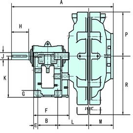
| Model | Outline Dimension | |||||||||||||
| A | B | C | D | E | F | G | n-d | H | J | K | L | M | N | |
| 25X20DM-A | 461 | 159 | 241 | 286 | 25 | 210 | 28 | 4-Ф18 | 57 | 20 | 145 | 89 | 90 | 86 |
| 75X50DM-B | 642 | 143 | 254 | 295 | 24 | 248 | 38 | 4-Ф14 | 80 | 28 | 197 | 191 | 136 | 114 |
| 100X75DM-C | 813 | 175 | 358 | 406 | 32 | 311 | 48 | 4-Ф19 | 120 | 42 | 254 | 253 | 163 | 146 |
| 150X100DM-D | 950 | 213 | 432 | 492 | 38 | 364 | 64 | 4-Ф22 | 163 | 65 | 330 | 280 | 187 | 190 |
| 200X150DM-E | 1218 | 257 | 546 | 622 | 54 | 448 | 76 | 4-Ф29 | 220 | 80 | 457 | 376 | 237 | 248 |
| 250X200DM-E | 1334 | 257 | 546 | 622 | 54 | 448 | 76 | 4-Ф29 | 220 | 80 | 457 | 413 | 306 | 292 |
| 300X250DM-S | 1406 | 490 | 560 | 680 | 50 | 590 | 70 | 4-Ф28 | 216 | 85 | 350 | 322 | 324 | 438 |
| 350X300DM-S | 1720 | 640 | 760 | 920 | 70 | 780 | 90 | 4-Ф35 | 280 | 120 | 450 | 415 | 300 | 475 |
| 400X350DM-S | 1776 | 640 | 760 | 920 | 70 | 780 | 90 | 4-Ф35 | 280 | 120 | 650 | 425 | 340 | 530 |
| 450X400DM(R)-ST | 1840 | 620 | 900 | 1150 | 80 | 780 | 125 | 4-Ф48 | 280 | 120 | 650 | 480 | 375 | 600 |
| 500X450DM(R)-ST | 1875 | 620 | 900 | 1150 | 80 | 780 | 125 | 4-Ф48 | 280 | 120 | 650 | 500 | 400 | 660 |
| 650X550DM(R)-TU | 2400 | 860 | 1200 | 1460 | 95 | 1050 | 150 | 4-Ф79 | 350 | 150 | 900 | 625 | 500 | 860 |
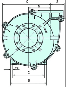
| Model | Pump Head Size | Inlet Flange Dimension | Outlet Flange Dimension | |||||||||
| S | Q | R | P | O.D | I.D | C-C BET. Holes | Holes | O.D | I.D | C-C BET. Holes | Holes | |
| 25X20DM-A | 144 | - | - | 128 | 114 | 25 | 83 | 4-Ф14 | 102 | 20 | 73 | 4-Ф14 |
| 75X50DM-B | - | 155 | - | 163 | 184 | 75 | 146 | 4-Ф19 | 165 | 50 | 127 | 4-Ф19 |
| 100X75DM-C | 102 | - | - | 204 | 229 | 100 | 191 | 4-Ф19 | 203 | 75 | 165 | 4-Ф19 |
| 150X100DM-D | 118 | - | - | 262 | 305 | 150 | 260 | 4-Ф22 | 229 | 100 | 191 | 4-Ф22 |
| 200X150DM-E | 155 | - | - | 324 | 368 | 200 | 324 | 4-Ф19 | 305 | 150 | 260 | 4-Ф19 |
| 250X200DM-E | 199 | - | - | 401 | 445 | 250 | 394 | 8-Ф22 | 382 | 200 | 337 | 8-Ф22 |
| 300X250DM-S | 257 | 476 | 603 | 470 | 552 | 305 | 495 | 8-Ф32 | 483 | 254 | 425 | 8-Ф22 |
| 350X300DM-S | 165 | 599 | 634 | 570 | 560 | 350 | 500 | 12-Ф26 | 530 | 300 | 470 | 12-Ф26 |
| 400X350DM-S | 295 | 643 | 691 | 620 | 640 | 400 | 580 | 12-Ф26 | 590 | 350 | 530 | 12-Ф26 |
| 450X400DM(R)-ST | 343 | 747 | 809 | 740 | 720 | 450 | 650 | 12-Ф33 | 685 | 400 | 615 | 12-Ф33 |
| 500X450DM(R)-ST | 375 | 814 | 872 | 800 | 770 | 500 | 700 | 12-Ф33 | 740 | 450 | 670 | 12-Ф33 |
| 650X550DM(R)-TU | 453 | 1055 | 1142 | 975 | 975 | 650 | 880 | 12-Ф39 | 900 | 350 | 800 | 12-Ф39 |